You have no items in your shopping cart.
Subtotal: $0.00
You have no items in your shopping cart.
On orders over $1500
(Continental United States only)
The Eurotherm 3200 series of controllers are available in the following DIN sizes 1/16 3216, 1/8 3208, 1/8 horizontal 32h8 and 1/43204 DIN panel sizes.


Let’s describe how the nanodac can be used to control the dosing level of a liquid or gas using the Feedforward feature of the PID algorithm to achieve an output proportional to the flow rate of the fluid.
Data Recorder with PID Control
The nanodac recorder/controller provides combined recording and control in a single ¼ DIN package.
The Nanodac is ideal for use on any application requiring up to four real universal inputs. In addition, fourteen inputs can also be written to over communications effectively making an 18 channel data logger. It also contains 2 PID control loops, which can be configured to control temperature, pressure, level, and process variables such as flow, etc,.
Additionaly, the nanodac recorder provides powerful logging and secure archiving of the data. It can store information in either or a secure (UHH), or open CSV format, or a check summed format to protect data integrity.
Also available is live trending, a simple menu allows any selected portion of the recorder history to be archived, either to a ‘memory stick’ plugged into the USB port at the rear of the recorder (Local Archiving) or to a computer or server, by means of the FTP protocol (Remote Archiving). This archived data remains in the flash (50MB) memory of the instrument and can be reviewed directly on the instrument display.
Archive period between the last hour, last day, last week, last month, can be chosen. Also one can archive everything in the recorders history or archive all files created since or updated since the last archive.
The archive status is displayed on the nanodac recorder/controller, which shows when data is being transferred or is complete. The archive data includes actual values from real or communications channels (PV), Alarm Messages, and Operator Input Messages. All of this information is accurately dated and time stamped from the on-board real time clock.
Residual control (Dosing)
Dosing or residual control, as it is also known, is the nomenclature given to the technique for controlling the addition of a substance to a flowing liquid or gas. Typically a dosing system is designed so that the required dosing level can be achieved by maintaining the control signal as a proportion of the fluid flow rate. The residual (dosing) level is used by the control algorithm to trim the output signal by the required amount. Any industry that mixes substances into flowing fluids potentially has the requirement for this type of control. These include the water, distilling, brewing, concrete, china clay, paper and soft drink industries or any process requiring disinfection in cooling towers, drinking water, food and beverage, swimming pools and wastewater.
Dosing Control Example

The figure above shows the general arrangement of the dosing control system which in this example uses chlorine as the dosing additive. The main fluid flow is measured upstream from the dosing pump, while the chlorine level is measured downstream. The feed forward feature in the control loop is used to achieve an output proportional to the fluid flow rate. This means that the dosing rate immediately tracks any changes in the flow rate and so avoids under or over dosing.
The dosing concentration, measured downstream, can be used to provide closed loop PID control action to trim the feed forward output. When the flow rate varies so will the transport delay of the control loop. To compensate for this, the integral time of the controller should be increased as the fluid flow rate reduces. This is achieved by using the Gain Scheduling feature of the nanodac recorder/controller. Three sets of control parameters are available, the active set selected according to the flow rate.
In some cases the dosing level to be controlled is further downstream from the dosing pump. This maybe by as much as fifteen to thirty minutes at normal flow rates. In these cases, providing the dosing level can also be measured much closer to the pump then the second loop in the nanodac recorder/controller can be used in cascade. The master loop controls the dosing level at the point further downstream. Process feedforward can still be used to compensate for flow rate changes.
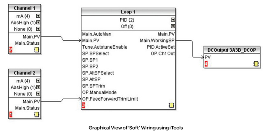
Internal ‘Soft’ Wiring
In the above example, dosing level is measured using channel 1 configured for 4-20mA input. It is connected to the main PV input of the control loop.
The flow rate is measured upstream using channel 2 configured for 4-20mA input, which is connected to the Feedforward input of the control loop.
The Control output is connected via Output Module 3. This is assumed to be 4-20mA in this example, but other outputs (such as on/off) may be used to match the type of pump in use.

They have a modular hardware construction which accepts up to three plug-in Input/Output modules and two interface modules to satisfy a wide range of control requirements. Two digital inputs and an optional alarm relay are included as part of the fixed hardware build. The instruments are available as:
Before proceeding, please read the Safety and EMC Information as follows:
This controller complies with the European Low Voltage Directive 2006/95/EC, by the application of the safety standard EN 61010. It is intended for industrial temperature and process control applications when it will meet the requirements of the European Directives on Safety and EMC. Use in other applications, or failure to observe the installation instructions of this handbook may impair the safety or EMC protection provided by the controller. It is the responsibility of the installer to ensure the safety and EMC of any particular installation.
The labels on the sides of the controller identify the ordering code, the serial number, and the wiring connections.
Understanding the Ordering Code
The 2408 and 2404 controllers have a modular hardware construction, which accepts up to three plug-in Input/Output modules and two communications modules to satisfy a wide range of control requirements. Two digital inputs and an optional alarm relay form part of the fixed hardware build. The ordering code is in two parts. The hardware coding and an optional configuration coding. The hardware coding specifies the basic build of the controller and the plug-in modules that are fitted


With the rapidly changing glass panels industry for cars, the complexity of shape and integration of sensors has been critical. As more demands for more stringent tolerances and the introduction of more complex forms and shapes, the automobile production process for glass panels has become extremely complex.

For example in a Tunnel Furnace where hundreds of sub zones, requiring precise and complex temperature control, running multiple recipes to allow maximum production, flexibility is a necessity. Resistive elements as well as medium wave infrared heaters have to be controlled to very tight parameters while maximizing energy efficiency.
Around the world, Eurotherm temperature control, power control and supervisory systems for windscreen forming are in operation. They provide:
In power glass applications, Eurotherm has always been present and successful:
The principle of windscreen forming is that the flat windscreen is going through a tunnel furnace on a very precise form. There is one type of form per type of windscreen. When at the right temperature, assisted by gravity the soft glass will take accurately to the form.
The pre-heating zone is the first part of the furnace where the temperature accurately controlled. The second part is the forming zone with a precise electrical power control. Heating elements are metallic resistors, medium wave infra-red, with a low temperature coefficient. Heat transfer to the windscreen is a combination of infra-red emission and air heating.
The quality and precision of the windscreen banding is given by the accuracy of forming zone power control and the accuracy of the pre-heating zone temperature controls.
On these furnaces, the number of zones can be very high, 100 to 300 zones. Present tendency is to increase the number of zones to improve precision of banding and to manufacture more complicated and various windscreen shapes. The total power of such furnaces can be several hundred kW to several MW.
Architecture of the installation

Millisecond set point transfer
On the furnace forming part, during process time each windscreen stays in a heating zone; its next working set point, for the next heating zone it will move into, is loaded in each EPower channel. When all the windscreens reach their next heating zone, a single command through the communication link will transfer in a few milliseconds all pre-loaded set points for each zone as an active set point.
Use this Eurotherm solution to your advantage
Checkout all our power controls at http://eurothermonline.com/power-controls.htmlhttp://eurothermonline.com/power-controls.html

The 3508 controller is supplied in the standard 1/8 DIN size (48 x 96mm front panel).
It is intended for permanent installation, for indoor use only, in an electrical panel, which encloses the rear housing, terminals and wiring on the back.
The functionality of controller depends on the features which have been ordered, see order code Section 1.2 below. Examples are:-
Programmer. A programmer varies the rate of change of setpoint allowing a profile to be set up.
Plug in modules. These provide customized input/output to plant devices.
The functionality of the controller also depends on how it has been configured. When it is first supplied the controller will enter a Quick Configuration mode which allows a basic set of features to be set up operation ‘out of the box’..png)
Further detailed configuration may be achieved either by using iTools configuration package or entering deeper levels of access. An Engineering Handbook, Part no. HA027988, provides a detailed description together with an explanation of terminology and may be ordered or downloaded from http://eurothermonline.com/instrumental-manuals/3500-series-manuals-and-brochures/
Section 1.2 Ordering Codes
The controller may have been ordered in accordance with the hardware code listed below. Additionally, it may have been ordered by quoting the ‘Quick Code’ listed in section 1.3. If ordered to the quick code the controller will be configured in the factory. If it is not ordered using the quick code then it will be necessary to configure the controller when it is first switched on.
Section 1.3 Quick Codes Use the tables below to determine your quick start code

To get assistance with ordering code, please call our office 800-849-5655, or use this form to contact us.
Two automatic tuning procedures are provided in the 2416:
• A one-shot tuner which automatically sets up the initial values of the parameters listed in Table 4-1 below. 
• Adaptive tuning which continuously monitors the error from setpoint and modifies the PID values if necessary.
One-shot Tuning:
The ‘one-shot’ tuner works by switching the output on and off to induce an oscillation in the measured value. From the amplitude and period of the oscillation, it calculates the tuning parameter values. If the process cannot tolerate full heating or cooling being applied during tuning, then the level of heating or cooling can be restricted by setting the heating and cooling power limits in the ‘oP’ list.
However, the measured value must oscillate to some degree for the tuner to be able to calculate values. A One-shot Tune can be performed at any time, but normally it is performed only once during the initial commissioning of the process. However, if the process under control subsequently becomes unstable (because its characteristics have changed), you can re-tune again for the new conditions.
It is best to start tuning with the process at ambient temperature. This allows the tuner to calculate more accurately the low cutback and high cutback values which restrict the amount of overshoot, or undershoot.
How to tune
1. Set the setpoint to the value at which you will normally operate the process.
2. In the ‘Atun’ list, select ‘tunE’ and set it to ‘on’.
3. Press the Page and Scroll buttons together to return to the Home display. The display will flash ‘tunE’ to indicate that tuning is in progress.
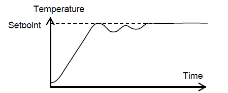
4. The controller induces an oscillation in the temperature by first turning the heating on, and then off. The first cycle is not complete until the measured value has reached the required setpoint.
5. After two cycles of oscillation the tuning is completed and the tuner switches itself off.
6. The controller then calculates the tuning parameters listed in Table 4-1 above, and resumes normal control action. If you want ‘Proportional only’, ‘PD’, or ‘PI’ control, you should set the ‘ti’ or ‘td’ parameters to OFF before commencing the tuning cycle. The tuner will leave them off and will not calculate a value for them.
Typical automatic tuning cycle
Calculation of the cutback values
Low cutback and High cutback are values that restrict the amount of overshoot or undershoot that occurs during large step changes in temperature (for example, under start-up conditions). If either low cutback, or high cutback, is set to ‘Auto’ the values are fixed at three times the proportional band, and are not changed during automatic tuning.
Adaptive tune
Adaptive tuning is a background algorithm, which continuously monitors the error from setpoint and analyses the control response during process disturbances. If the algorithm recognizes an oscillatory, or under-damped, response it recalculates the Pb, ti and td values. Adaptive tune is triggered whenever the error from setpoint exceeds a trigger level. This trigger level is set in the parameter ‘drA.t’, which is found in the Autotune list. The value is in display units. It is automatically set by the controller, but can also be manually re-adjusted. Adaptive tune should be used with:
1. Processes whose characteristics change as a result of changes in the load, or setpoint.
2. Processes that cannot tolerate the oscillation induced by a One-shot tune.
Adaptive tune should not be used:
1. Where the process is subjected to regular external disturbances that could mislead the adaptive tuner.
2. For highly interactive multi-loop applications.
However, moderately interactive loops, such as multi-zone extruders, should not give a problem.
MANUAL TUNING
If for any reason automatic tuning gives unsatisfactory results, you can tune the controller manually. There are a number of standard methods for manual tuning. The one described here is the Ziegler-Nichols method.
With the process at its normal running temperature:
1. Set the Integral Time ‘ti’ and the Derivative Time ‘td’ to OFF.
2. Set High Cutback and Low Cutback, ‘Hcb’ and ‘Lcb’, to ‘Auto’.
3. Ignore the fact that the temperature may not settle precisely at the setpoint.
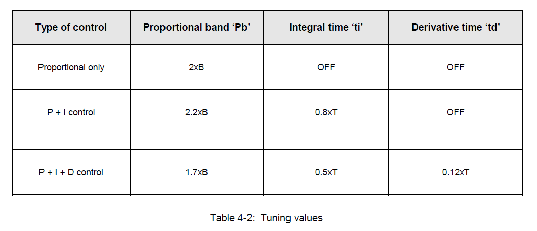
4. If the temperature is stable, reduce the proportional band ‘Pb’ so that the temperature just starts to oscillate. If the temperature is already oscillating, increase the proportional band until it just stops oscillating. Allow enough time between each adjustment for the loop to stabilize. Make a note of the proportional band value ‘B’ and the period of oscillation ‘T’.
5. Set the Pb, tiand td parameter values according to the calculations given in
Software version 5 and above of the 2604 controller supports Master Communications. The objective of the master comms is to allow the 2604 to communicate with any instrument using ModBus interface as a master device, that is, without the need for a supervisory PC. This allows the 2604 to link through digital communications with other products to create a small system solution.
There are two methods of communication
1. Broadcast Communications
2. Direct Read/Write
Broadcast Communications
The 2604 master can be connected to up to 32 slaves. The master sends a unit address of 0 followed by the address of the parameter which is to be sent. A typical example might be a multi zone oven where the setpoint of each zone is required to follow, with digital accuracy, the setpoint of a master.
Direct read/write
The 2604 master can be connected to up to eight slaves. Each slave has its own unit address. The master can send data to each slave by sending a unit address followed by the parameter address. It can also request data from a slave. This data may be displayed on the 2604 or used as part of a 2604 control strategy.
During the life of the product, the Service and Repair activity monitor the level of repairs and use of spares.
As a minimum this activity must start no later than when the product is moved from 'Current' to 'Available' classification.
This information is used to help predict the spares stock holding requirements.
The review and definition of product status is carried out as required.
Purchasing, Manufacturing, Service Centre and Customer Support communicate, to the Portfolio Manager, any on-going issues that affect the ability of Eurotherm to continue the manufacture and supply of any product currently in the 'available' category, and during the 'Lifetime’ category to maintain Service Support. In such an instance a series of additional reviews are convened to monitor the situation and decide upon any extraordinary actions necessary. This may result in the premature entry of an instrument into an obsolescence category.
Basic Obsolescence Timing:
Progression through each phase of obsolescence requires acceptance of the plan by Marketing Director, Sales Director, R&D Director and Portfolio Manager.
Current / Preferred - ‘Level 1’ - Under Review'
Notification of Level 1 status is distributed to UK Sales and Service and Group Companies.
There is no feature development of products unless it affects safety or is to rectify field failures.
Alternative product offerings are identified. There may be a number of alternatives, depending upon the capabilities of the alternatives available. Definition of alternatives should include all information required to install the replacement instrument in place of the original. This includes cross-reference wiring information from one instrument to the other and operating instructions.
Availability - ‘Level 2’ – No longer available but may be by Special Order Only: The following products are in this category: 7200A, 7300A Full, 7300A Light , Continental Solid State Relays & IO Modules Special orders & repairs only
Some, but not all, replacements are scheduled for December 2016
Notification of Level 2 status is distributed to UK Sales and Service and Group Companies.
Lists of all known users, during the last two years, of the product to be provided to the Sales Engineers, Group Companies and direct to 'Third Party' operations as appropriate, together with personalized copies of a letter detailing status of the product in question and the possible alternatives.
In the UK, after three months all customers not yet contacted by the Sales Engineer to be contacted directly from Worthing England with a personalized letter detailing status of the product in question and defining recommended alternatives.
Purchasing need to be informed and demand (forecast) amended. Any last time buy requirements to be collated by UK Service center.
Apart from supporting documentation in the document library, all product promotional material is removed from the website.
Mature and Lifetime Care – ‘Level 3’ No Longer Available.' The following products are in this category:
7100A Light, 7100S, 7200S, 7300S, TE10S, TE200S, TE200A, TC2000 repairs only
Replacements scheduled for December 2016
Continue to promote alternative replacement products - include a notice in each repair returned.
Product Availability: None
Spares Availability: Limited for Service activities only.
Product should be removed from Sales Order Processing System and assemblies made obsolete.
Obsolete - ‘Level 4’ - Beyond Economical Repair
Continue to promote obsolescence status of the product and offer advantages of replacement with the alternatives available. Support is very limited, affected by spares stocks and replacement parts availability.

The 3504 controller is supplied in the standard ¼ DIN size (96 x 96mm front panel). The 3504 Controller contains up to six plug-in hardware modules; the 3508 Controller has up to three. Moreover, digital communications modules can be fitted in two positions.
These modules provide an interface to a wide range of plant devices and those fitted to it are identified by an ordering code printed on a label to the side of the instrument. This code defines the basic functionality of the instrument which may be: